What Happens to the Tube in the Bend?
Every bend asks the same three things of the tube. The outside stretches and thins, the inside compresses and can wrinkle, and the round section tends to flatten towards an oval. Tighter radii and thinner walls make each of these harder to control, because there is less material to resist and less wall for the tooling to support.
UltraTube™ is made from dual-phase steel, a soft ferrite matrix with harder martensite, which gives it high strength together with good formability. The bend still depends on controlling how the tube deforms, and that is what the rest of this article addresses.
One rule is specific to this class of steel: bend it cold. Torch heating or heat-assisted bending can locally temper the dual-phase microstructure and reduce strength. Packed sand and low-melt alloy fillers, which are intended for hot bending, are also not recommended.
Choosing the Bend Radius
Radius is normally specified at the tube centreline (CLR) as a multiple of the outside diameter (D). On 38.1 mm tube, a 2D radius is 76.2 mm and a 3D radius is 114.3 mm. Bend angle is separate: either radius can describe a 180° bend.
Our general recommendation is 3D or greater, particularly for thin-wall tube and for equipment without a mandrel. A larger radius reduces the forming demand and gives the workshop more scope to control the cross-section. Tighter bends are possible with suitable tooling, as the trials below show, but they depend on tube diameter, wall thickness, die condition and setup.
Find out which die radii are available before finalising the design, whether in your own workshop or at the bending shop you use. The dies set the radius you can actually bend. For motorsport builds, check the requirements of the relevant sanctioning body for the vehicle and category. MotorSport New Zealand’s Schedule A, for example, specifies a minimum 3D centreline radius (CLR) for main and lateral rollbars. Where a minimum radius is prescribed, UltraTube’s ability to achieve tighter bends does not override it, and material eligibility and cage approval must still be confirmed for the application.
Positioning the Weld Seam
For a straightforward bend, position the longitudinal production seam at the side of the tube, on the neutral axis. This keeps it away from the greatest stretching on the outside and the greatest compression on the inside. Mark the orientation so it can be repeated each time a length is loaded.
What the UltraTube™ Bend Trials Showed
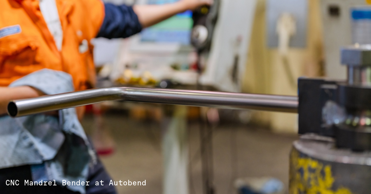
UltraTube™ RS was bent by three independent workshops on different equipment. Racecraft Engineering (rotary-draw, mandrel) and Mitchell Race Xtreme (ProTools mechanical bender, unsupported) bent at the standard 3D radius their dies are built for in motorsport work. Autobend’s CNC mandrel bender went tighter to test seam integrity and formability, completing 180° bends at 2D CLR with the seam on the neutral axis, in compression (inner radius) and in tension (outer radius). The latter two orientations were used deliberately to test the tube under adverse conditions and demonstrate the integrity of the production seam. They are not a recommended practice.
All samples completed the bends without cracking, surface tearing or excessive distortion. Mandrel-assisted bends delivered near-perfect geometry. On the unsupported ProTools bender, 1.6 mm wall tube showed some visible ovalisation but remained within 10% of the tube OD. That is typical of external-die-only bending, including with 4130 CrMo, and the results were consistent with or better than those typically achieved with seamless 4130.
These results demonstrate the capability of the tested samples and setups. Side positioning remains the recommended starting point for routine fabrication.
A: 180° bends with a 2D centreline radius, formed by Autobend, showing the production seam positioned on the neutral axis, on the inside of the bend (compression), and on the outside of the bend (tension).
B: 70° bends at a 3D centreline radius, formed by Mitchell Race Xtreme using a ProTools hand bender